The Magnetic Loop antenna has always been a fascinating antenna for me, different from the classic wire or dipole stretched in the air. Despite its small size, compared to a full size dipole of the same frequency, the Magnetic Loop holds its own, and with a few tricks will not make us regret the dipole.
Certainly, the ML has advantages in terms of size, bandwidth, portability, etc., but on the other hand it has some points that often discourage those who want to try their hand at DIY.
The main problem, especially if we want our antenna to resonate over a wide frequency spectrum, is to find a variable capacitor that is reliable enough and capable of supporting a discrete voltage between the armatures. In fact, voltages of the order of thousands of kV can be obtained between the armatures of the capacitor with only 15/20 W. Precisely because of the high voltage present at the ends of the capacitor, it is necessary to connect the parts in the best possible way in order to limit transmission losses, avoiding too many connections one after the other, where a certain amount of RF would be uselessly wasted.
In fact, this was not my first home-made ML; in the past, not being able to mount normal antennas, I had to resort to an ML on my balcony at home.
At the moment I needed an antenna that was efficient, did not take up much space and could even be used indoors on some business trips.
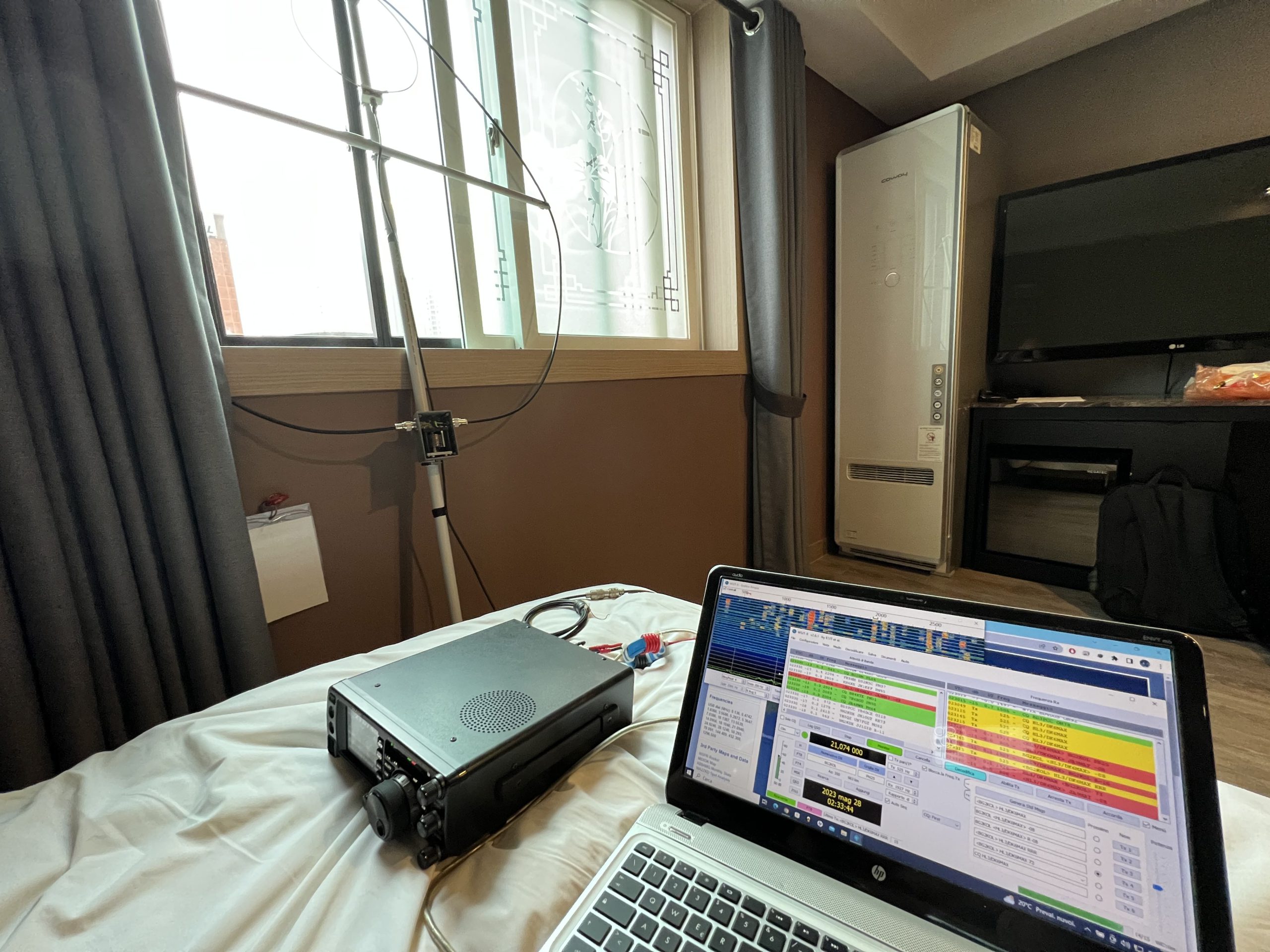
What came out first was the ‘circle’ you see in the picture. I took it with me to South Korea and made a few QSOs from the hotel where I was staying, but frankly, using it, I immediately realised its limitations.
The loop on this first model was made from coaxial cable that was too soft. I had to add a horizontal support to keep the loop almost round. I had tried to copy the construction from an OM website on the Internet; his loop was stiff, yes, but it was cut at the top. In practice, the radiating part was the core of the coax cable, so that it’s screen needed a cut of a few centimetres at the top to work. I didn’t get any benefit from this, on the contrary, the bandwidth was reduced and of course the efficiency too, because I had to use a wire of a few mm diameter instead of the 10.3 mm diameter of the coaxial cable screen.
None of this allowed me to work at 10 metres. The second sore point was the heart of the loop: the variable capacitor. The armatures were too close together to allow me to use more than 10/12 W in the FT8 mode, and frequency tuning was a real nightmare: every time I wanted to QSY, I lost tens of minutes re-tuning the variable capacitor. Also, as soon as I got my hand close to the variable, the tuning quickly went off.
So when I returned home, I decided that I had to solve the problems on this loop, or at least limit them.
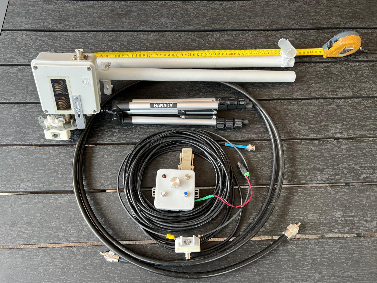
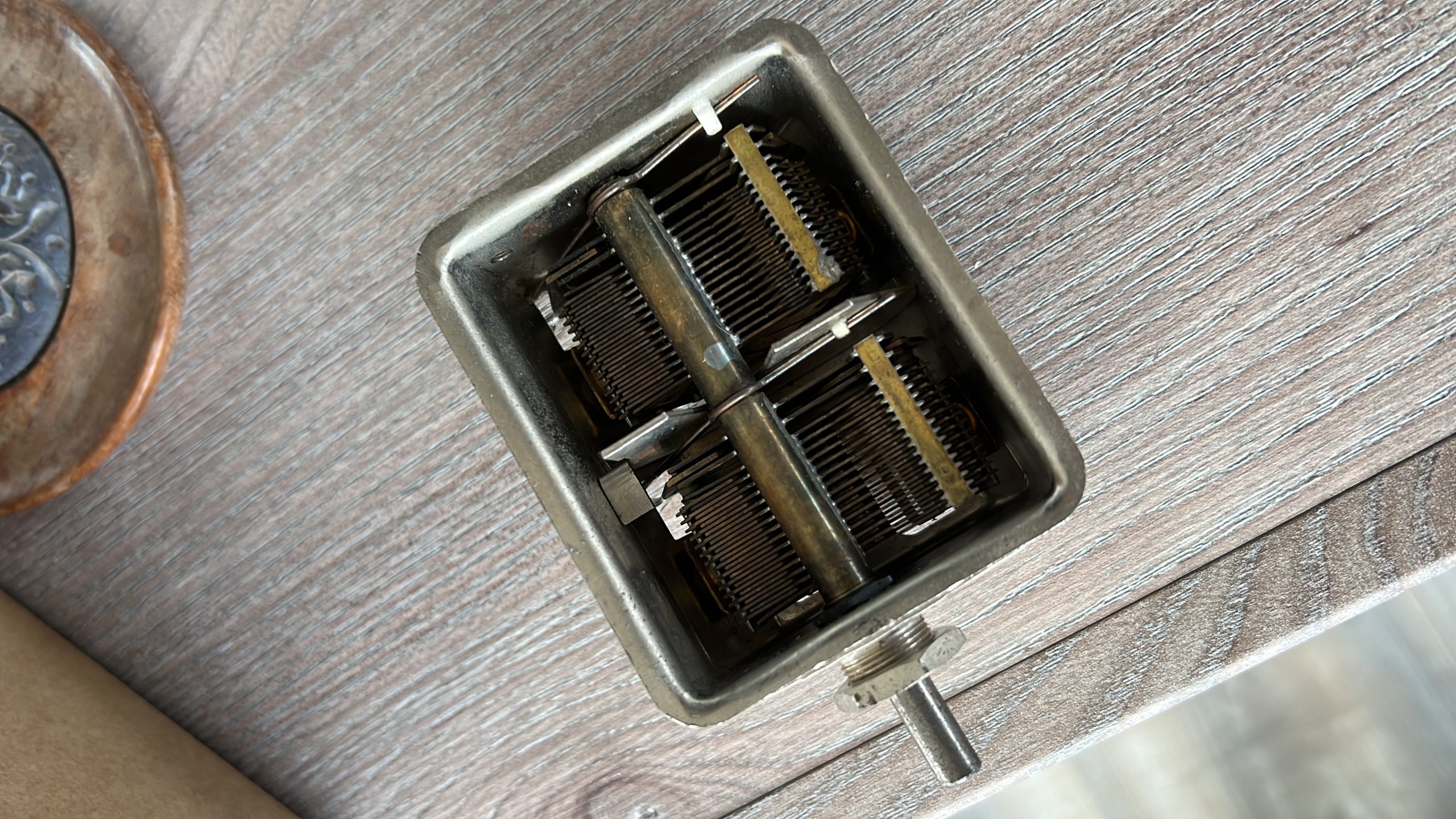
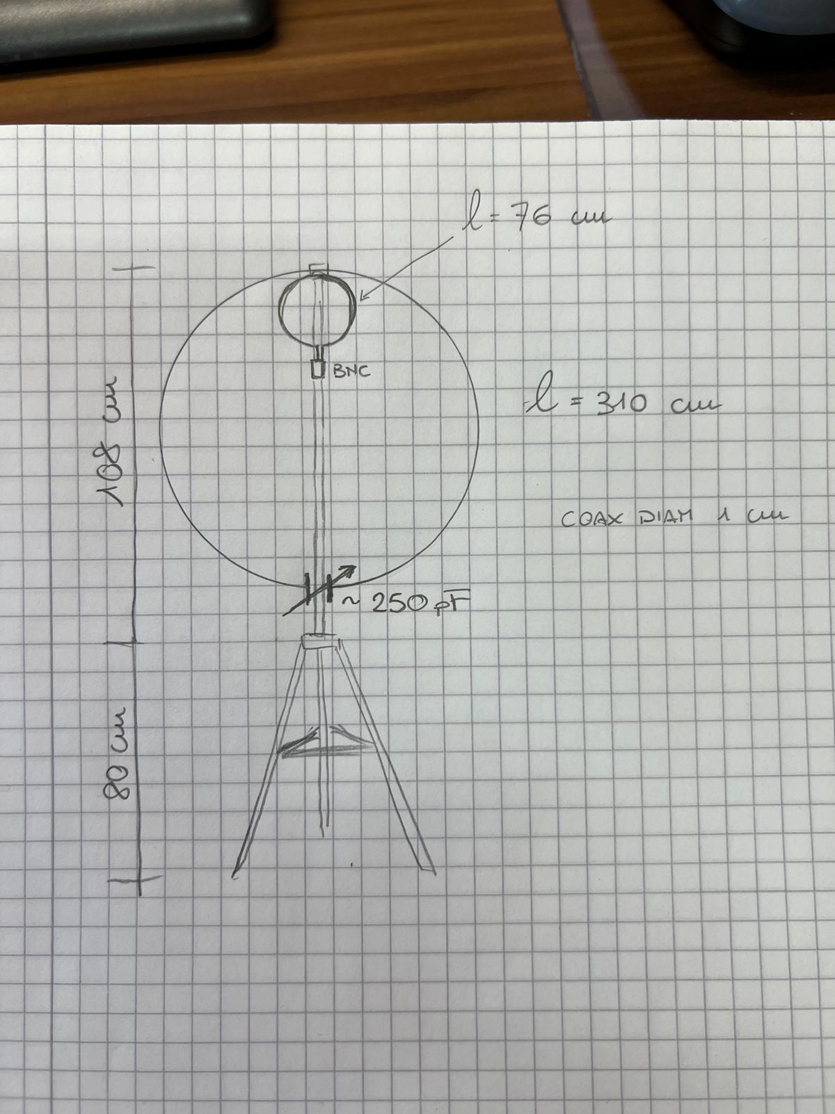
First I found a nice piece of H1000 with a rigid core in my garage. I searched the internet for a more reliable variable capacitor of around 250 pF. I found the one in the photo on e-bay, simply great! The capacitor is a double one (250+250 pF) without sliding contacts, this allows you to double the usable power while maintaining a higher efficiency compared to the old capacitor which was a single one with sliding contacts.
Finally, I no longer wanted to get up every time I wanted to QSY and go crazy tuning the ML, also because I preferred to have the antenna as far away from my body as possible during transmissions.
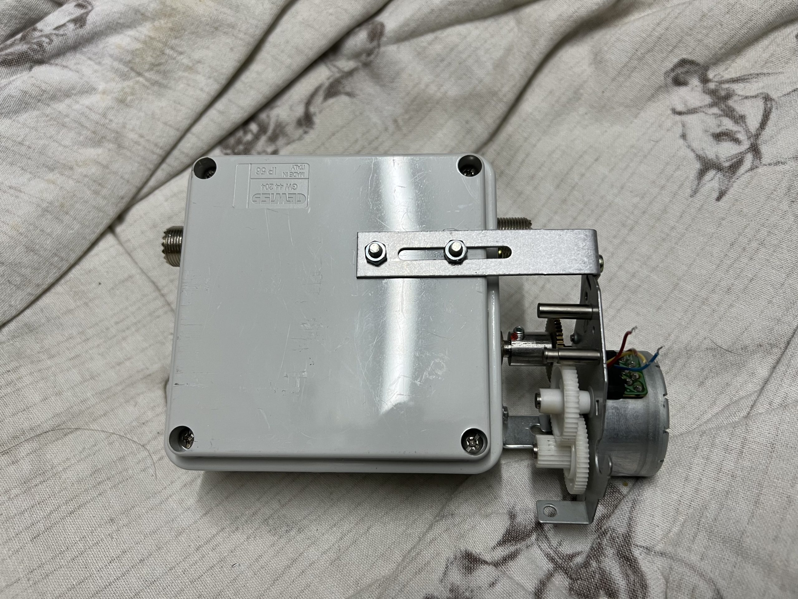
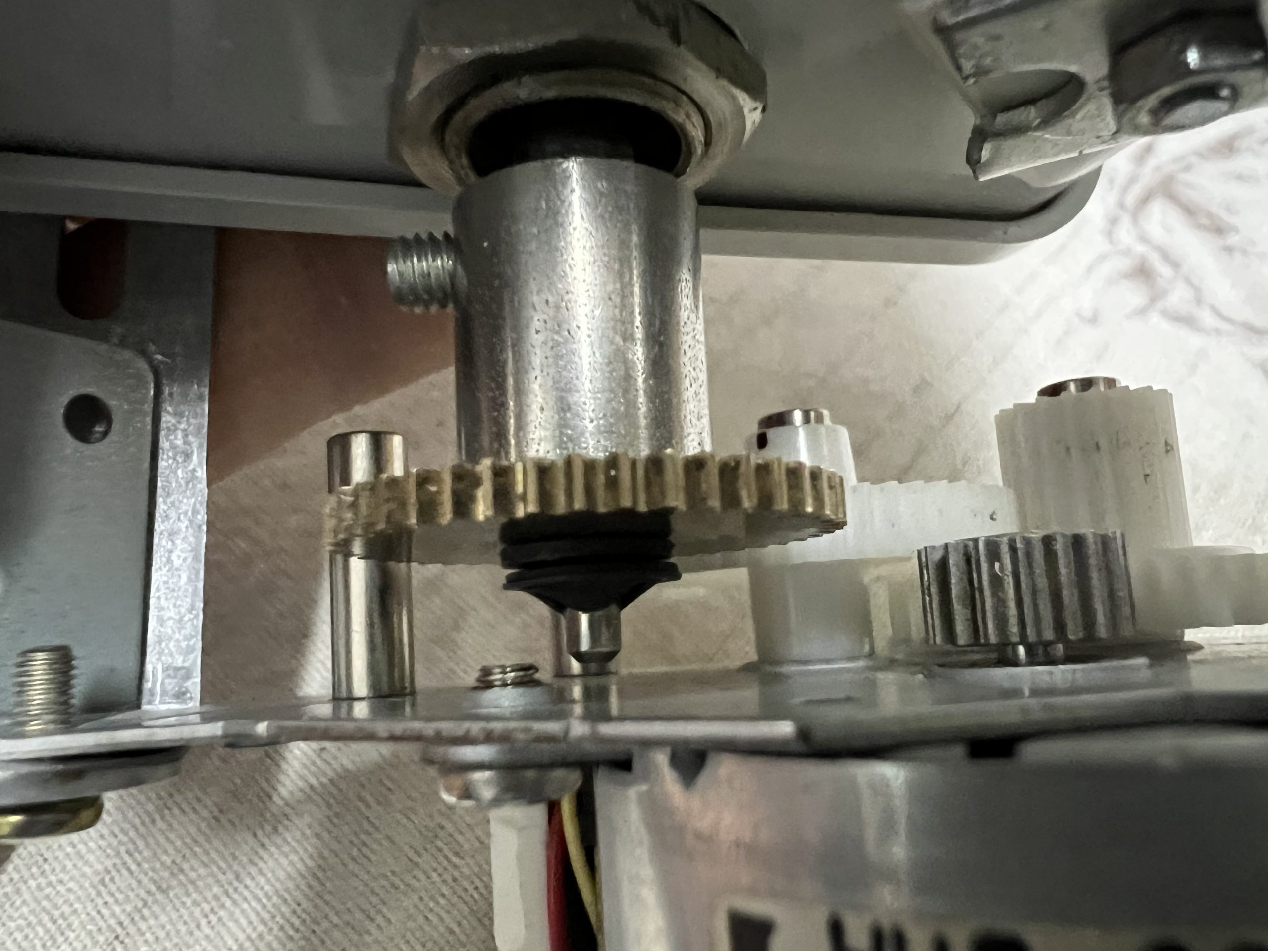
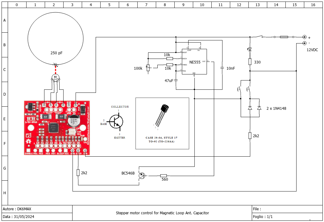
I found a stepper motor with a gearbox in my little laboratory, attached the mechanical part to the side of the box containing the variable capacitor and created a small “remote control” with wire to move the small motor back and forth with just the press of two buttons.
The interesting thing is that the gear on the variable capacitor axis is clutched, so I’m not having any problems getting the capacitor to stop mechanically.
There is no risk of anything breaking.
The electrical connection to the motor was made with normal cat5 Ethernet cable, which allows the remote control to be attached and detached from the motor in 2 seconds.
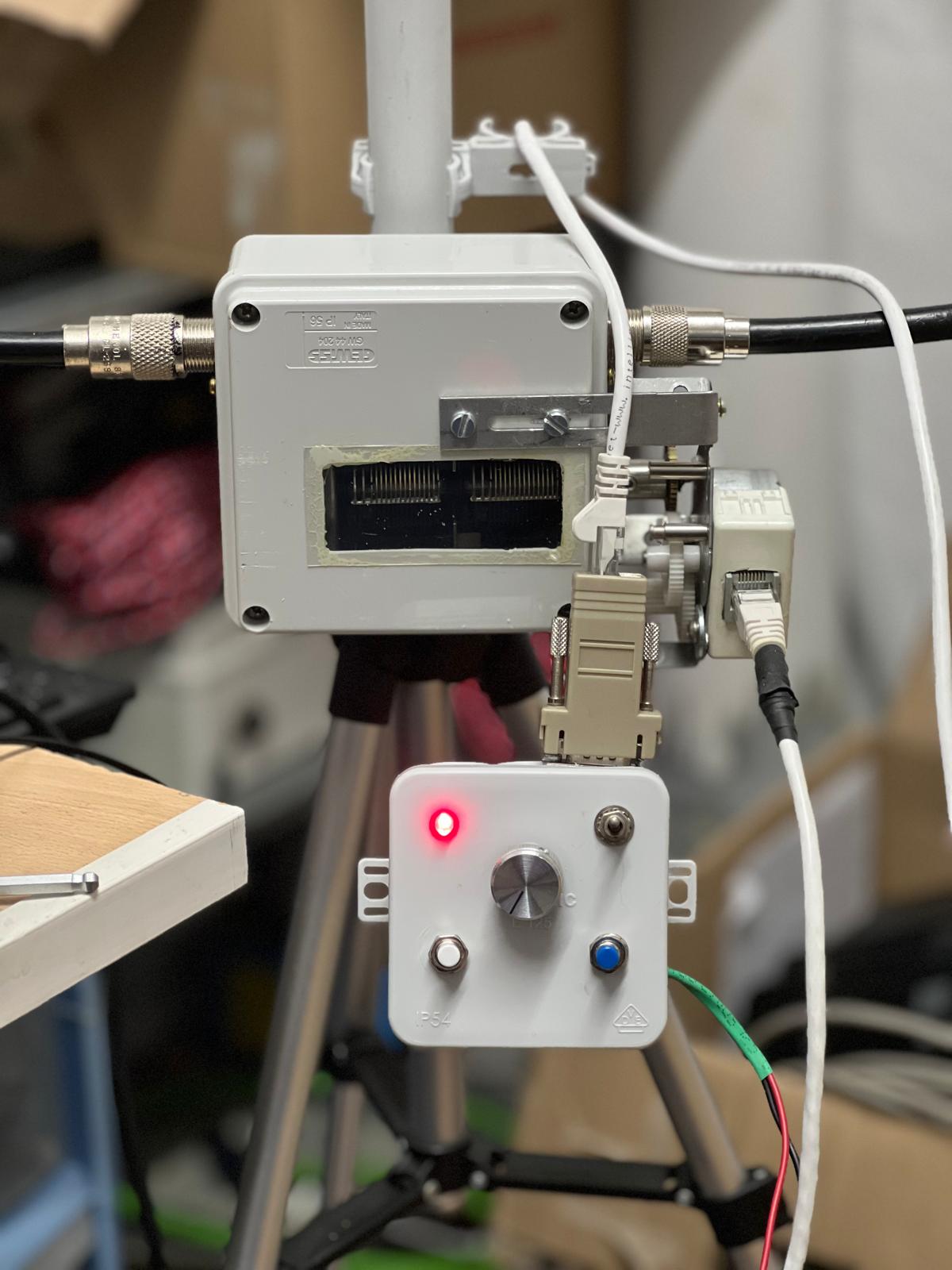
At the end of the construction, I thought of opening a small window in the lid of the variable capacitor so that I could see its movement and any electrical sparks during transmission.
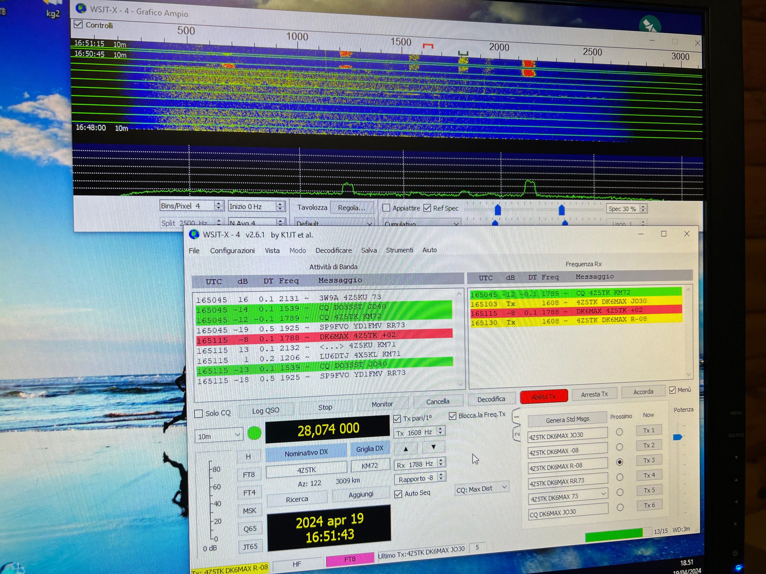
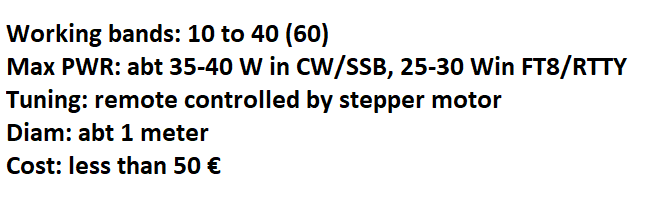
I then carried out some transmission tests, of course. The first ever inside my radio station, first shot Israel, 4Z5TK, in 10 FT8 with 10 watts, not bad.
Then the official test was during the last ARI DX. Not having antennas ready for 10, 15 and 20 metres, I tried a few QSOs with the loop and 30 W on CW. Not bad at all, considering that the antenna was between the house and the radio station, so not in a very open place. I made about 70 QSO’s.
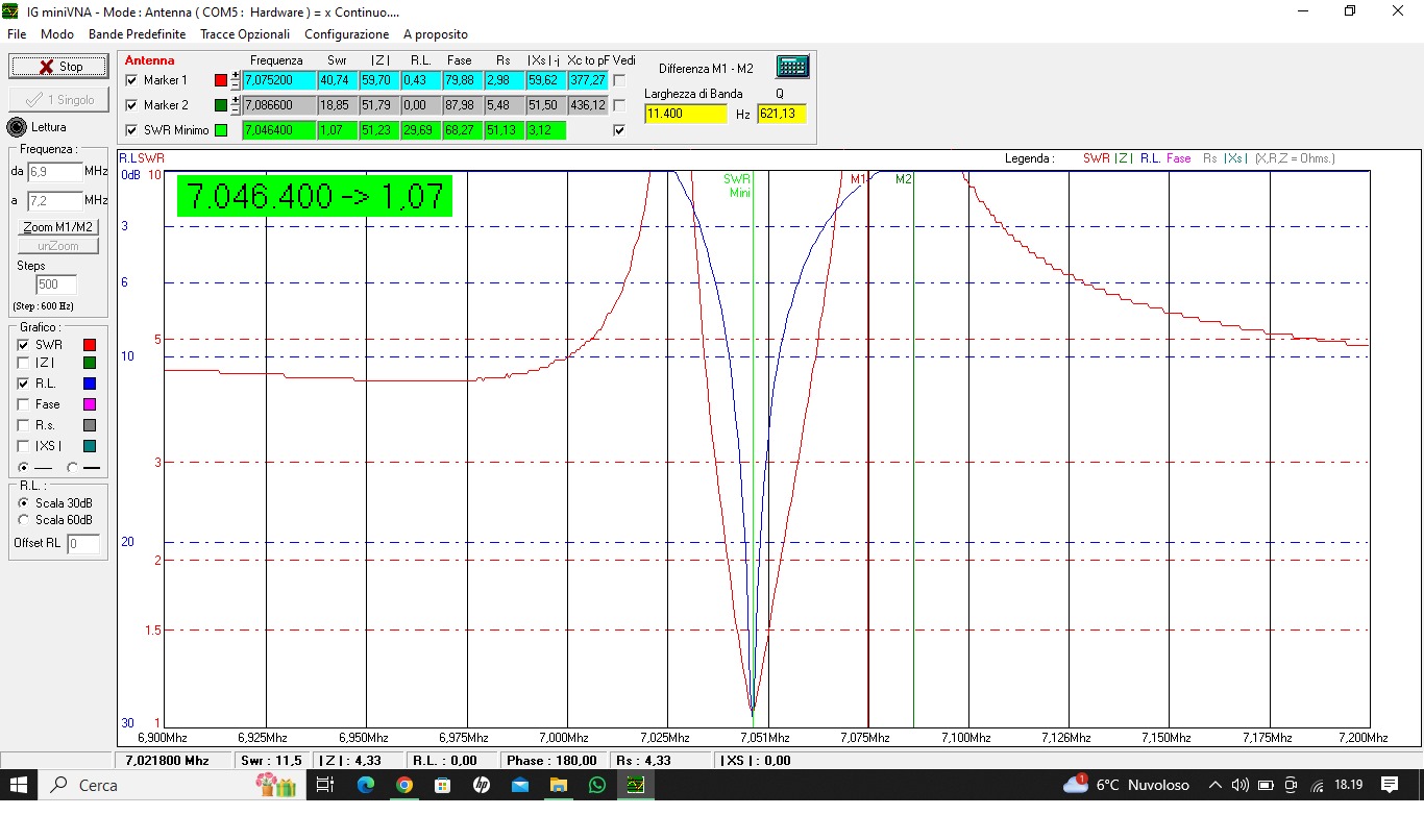
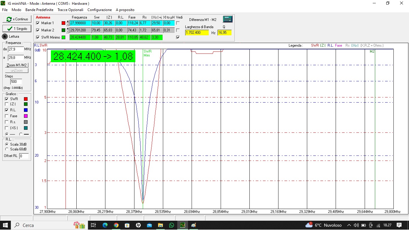
Below is the SWR at 10 and 40 during home testing:
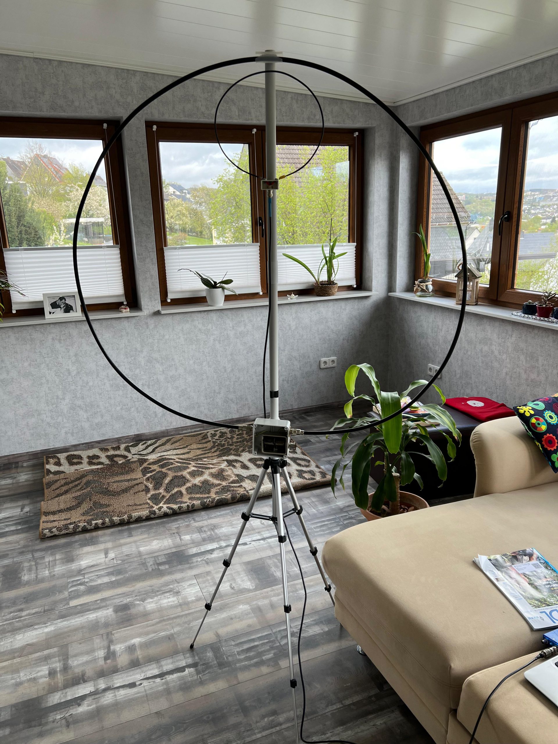
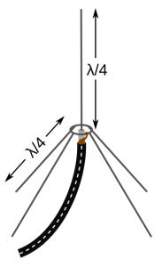
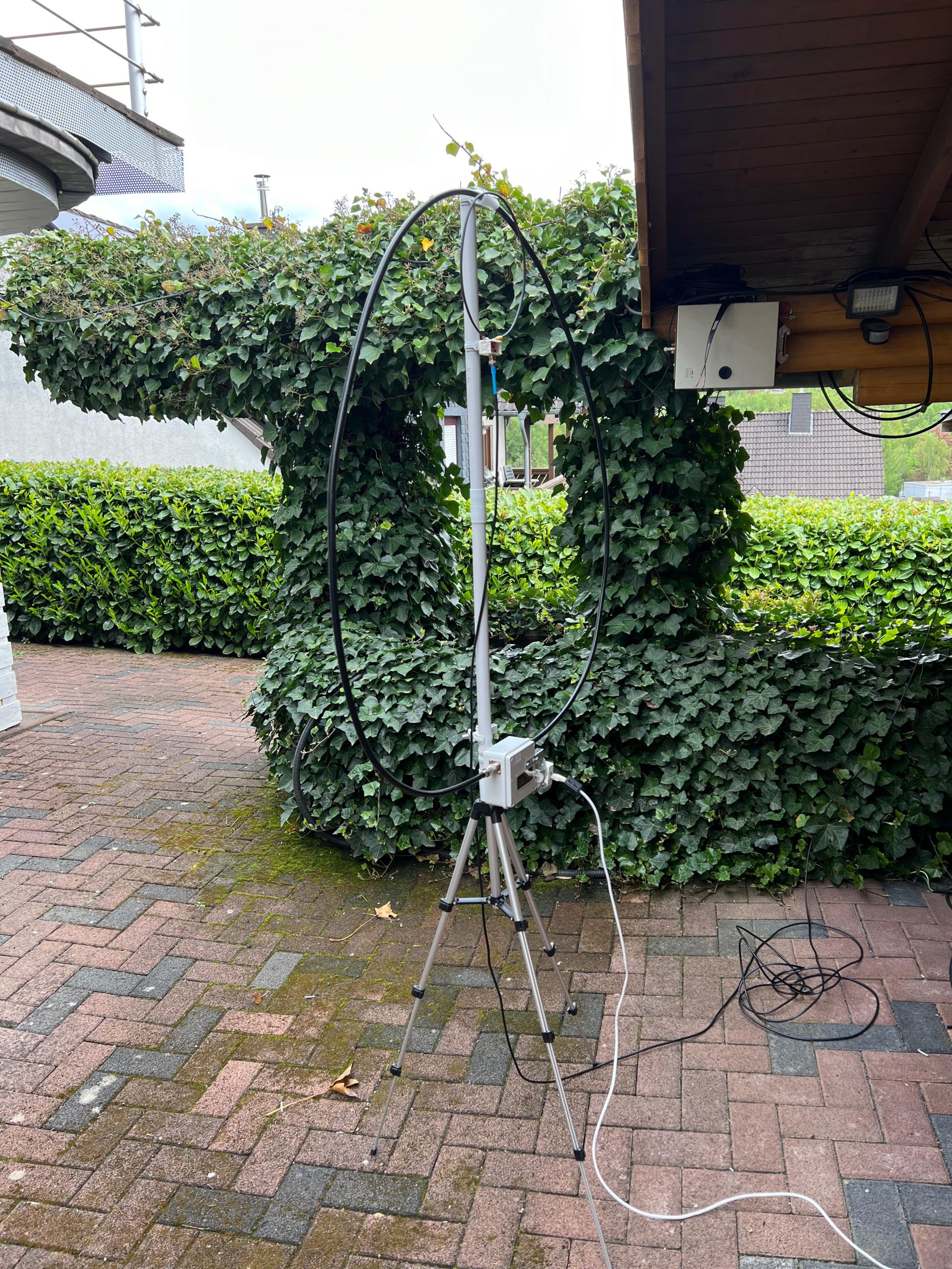
Depending on the position of the loop, it is very important to be able to move the small loop closer to or further away from the large loop in order to achieve optimum impedance. In fact, I have noticed that on the inside it is necessary to distance them, while on the outside it is necessary to bring them closer together and overlap them.
To finish, I will add the dimensions of the loop and the circuit used to turn the capacitor. It is not beautiful to look at but I hope it will be sufficiently useful for those who want to try their hand at construction.
The potentiometer on the remote control allows you to vary the step speed from 0.3 to about 1 second per step.
The driver for the stepper is a BigEasyStep configured as 1/32 microsteps, but any other driver can be used.
The support was made from 25mm PVC pipe for electrical installations.
Further modifications can be made, such as using a wireless control or connecting the controller to the radio so that tuning is done automatically, it is not complicated.
Happy building and great QSOs to all!