These days, I have finished rebuilding the radio system to operate on the QO100 geostationary satellite. There are two major changes in this new configuration.
In the old system I used two separate dishes, one for transmitting with a diameter of 80 cm and a second one for receiving with a diameter of 100 cm, using the TV dish.
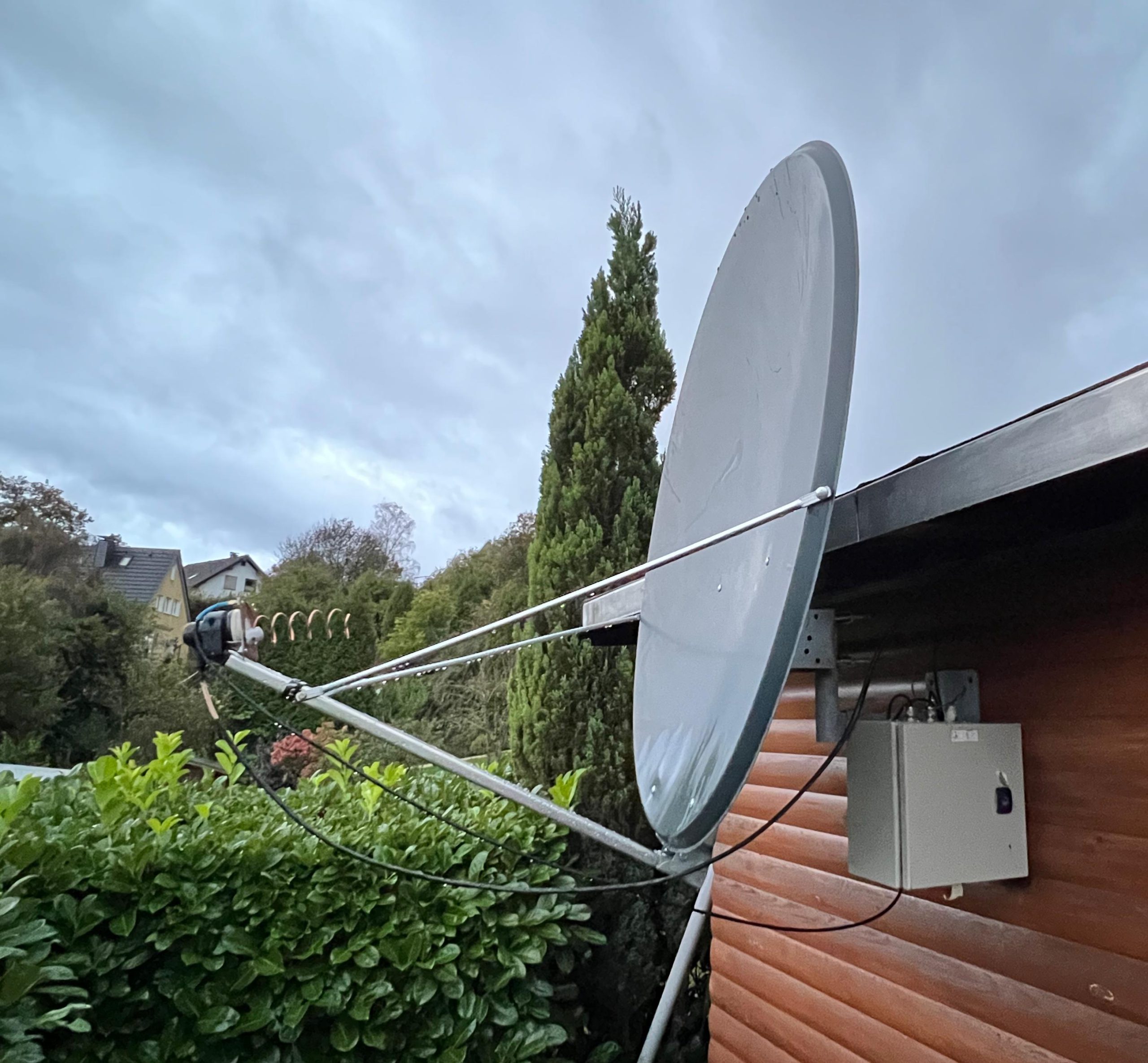
In this new configuration I wanted to try a single 120 cm dish, with a slightly higher gain than the previous one. The theoretical gain (without Helix) of an 80 cm dish at 2.4 GHz is almost 24 dB, whereas the 120 cm dish has a gain of 27.4 dB. This means that I have gained over 3 dB just by changing the transmission dish, which is equivalent to doubling the transmission power.
The transmission system in terms of radio, converter and 3 watt amplifier has not changed, everything is more or less the same, apart from the wiring.
The first tests were carried out with my old TX feeder consisting of a 5-turn Helix antenna. Knowing that I would have more input power on the transponder, I used the same system as before to attenuate the excess power output from my 991A and adjust it to my liking. So about 12 metres of plain RG58 runs from the radio to the input of the DX-Patrol converter. This way, with about 15 Watts output from the 991A, I end up with about 5/6 Watts at the converter input.
From the first tests, after the dish was perfectly aligned, I noticed that my power on the satellite was much higher than before, so much so that the transponder control buzzer was triggered for excess power. With sufficient attenuation via the RG58 cable, I was able to easily manage the EIRP power via the 991A’s output, bringing it down to perfectly acceptable levels.
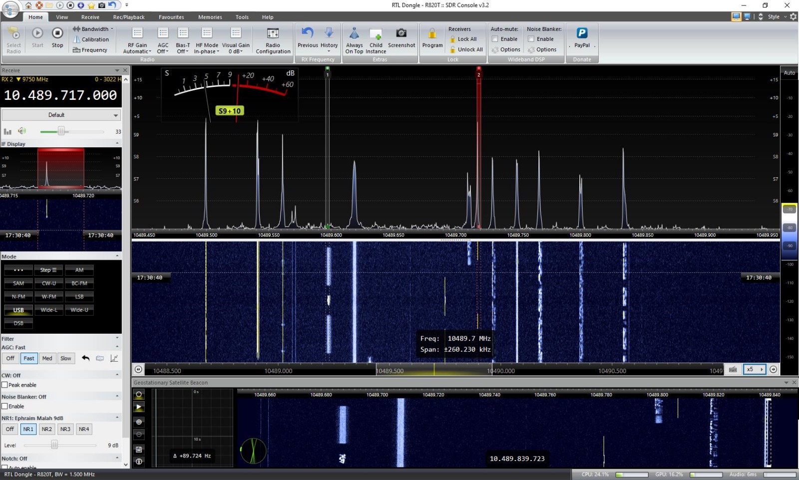
But even though I made a few QSOs on SSB and CW that evening, I still didn’t have MY receiver, I was using an online SDR and I didn’t like it at all.
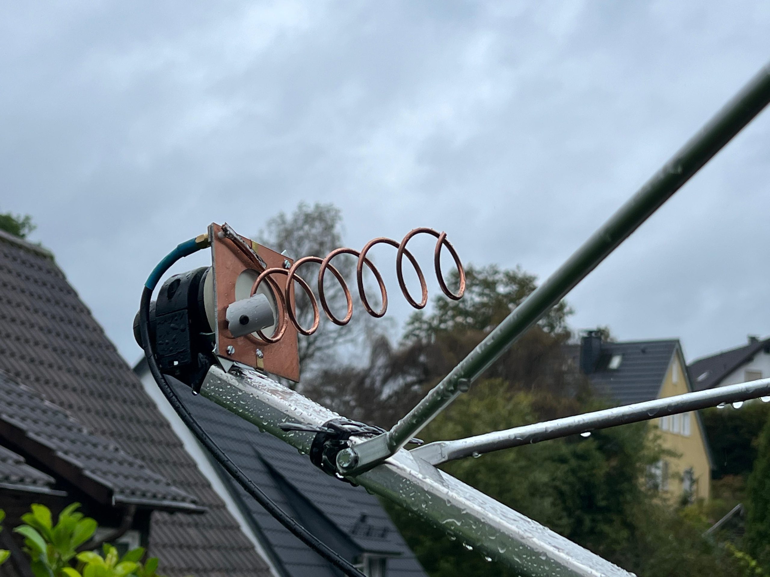
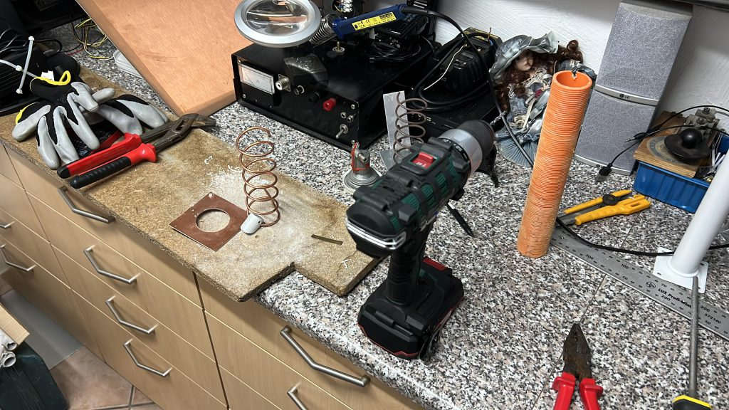
Within a few hours one morning I started building a new Helix, but this time with a double-sided copper-plated bakelite reflector. The main problems were basically two: where to put the connector for the Helix coax, and how to put the LNB behind the reflector. Would this have worked? I had seen some interesting things on the internet, but they required at least a 3D printer, which I don’t currently have. However, not having many options, I mounted the reflector (and thus the helix) directly on the LNB. I thought a 32mm hole would be enough to pass the reflected signal from the dish.
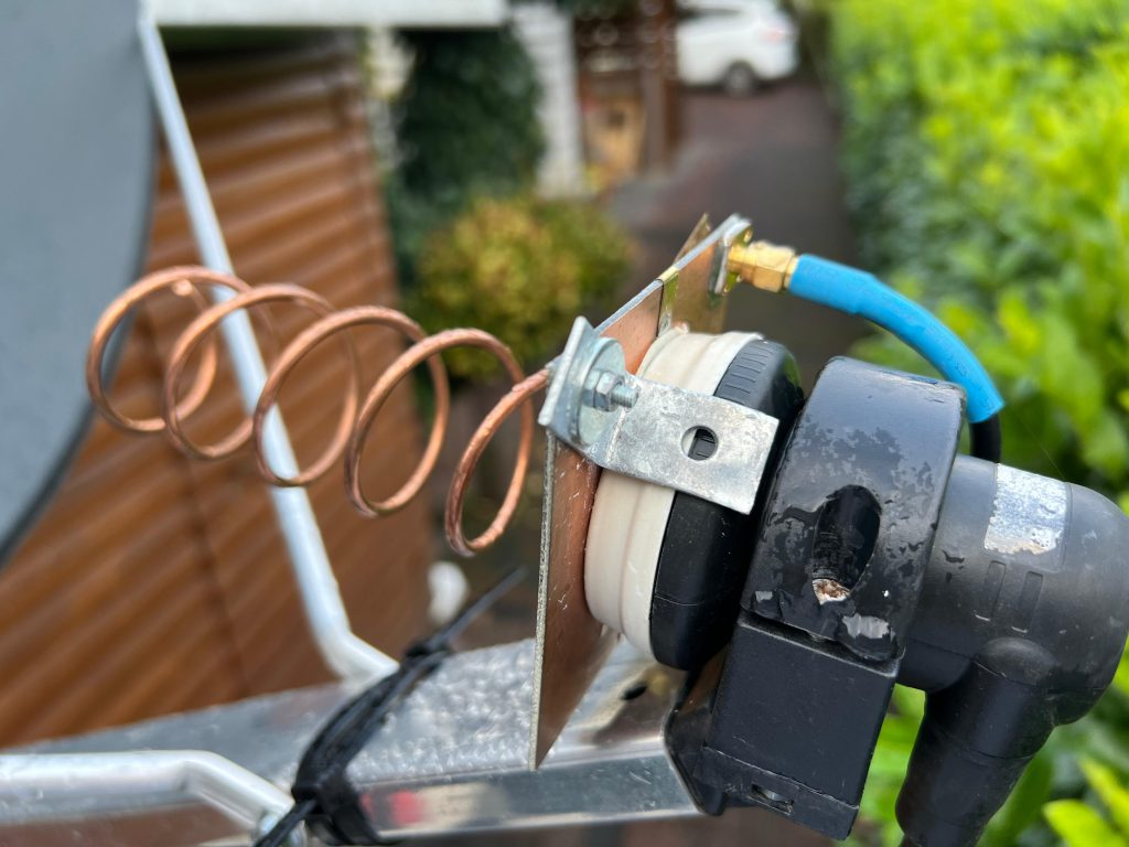
However, I had doubts about the power supply point and the impedance matching of the Helix. The idea was to simply “twist” the copper rod with the foil soldered to it towards one of the corners of the reflector to match the 140 ohms to the 50 or so required. I haven’t tested the antenna with a VNA yet and I hope to do so soon to see how it really behaves… but…
Once everything was assembled, I mounted the dual coaxial feed on the focus of the dish. I was delighted to see that the reception signal was fantastic and of exceptional quality! The same was true of my signal on the transponder, apart from a small drop in power of about 2 dB.
I’m already working out how I can move the dual feed back a bit to get the same signal as the single Helix.
Will update!