From my original post of 12-04-2010, on Hamradioweb.org.
On the Hamradioweb.org forum there have been a number of posts concerning the attenuation of interference from closely spaced stations on adjacent bands in the case of multi-transmitter operations, such as contests and expeditions; the curiosity of some has prompted me to write these few unpretentious notes, aimed mostly at the uninitiated, about what coax stubs are and how they are constructed.
I will not deal with any particular formulas, but I will refer to a few values just to give some numbers on which to reason.
Scenario: two transceivers, two antennas, two different bands, simultaneous operation.
According to calculations made on modern receivers, the highest power of a signal that can be received without damage from the front-end is about 50 mW (or 17 dBm).
For comparison, consider that a signal at S 9+60 corresponds to about 50 uW (microWatts).
When two transceivers have their corresponding antennas relatively close to each other, the signal picked up by the adjacent transceiver can be considerably higher than 50mW, definitely causing damage to the receiving circuit; this is because modern transceivers have very wide filters and, although they attenuate harmonics according to the law, in our case they fail to attenuate them sufficiently and not radiate (pick up) other annoying and ‘dangerous’ signals a little over all HF. The latter are caused for intrinsic technical reasons by the transmitters themselves (e.g. phase noise, broadband noise).
Reducing the interfering signal for the sole purpose of not damaging a receiver does not help in simultaneous operation. Having a continuous disturbance at S8 would not allow for easy operations. In fact, without going too much into other specifics, the goal to be achieved in a station with such characteristics is to reduce interference as much as possible, and perhaps as low as -135dBm, the noise floor, i.e. generally the lowest signal perceptible by a receiver, this is determined by the circuitry dedicated to reception.
First solutions
The first thing we can do is to reduce the power, which would certainly allow easier operation at the expense, in some cases, of transmission performance. Neighbouring QRP stations, on adjacent bands, are unlikely to annoy each other.
The second thing available to us is to move the antennas away from each other, or at least turn the directives so that the main lobes do not point at neighbouring antennas. But even this is not possible most of the time: we have to work one station in the direction of the other antenna, we often do not have enough space to space the antennas apart (small islands, land or apartment building stations), and almost all contests oblige us to transmit in a relatively confined space (so no multi everyone at home).
We can reduce interference by using different polarisations for the two antenna systems, which can be further improved if we use monoband antennas as their characteristics deteriorate outside the working frequency.
Filter filter…
A very good help is to reduce interference by filtering out unwanted signals. This can be done with commercial or DIY bandpass filters (the latter successfully tested) and/or precisely with stubs made from coaxial cable. The
substantial difference between a PB and a stub lies in the fact that while the former attenuates everything but the working band, the latter attenuates only some unwanted bands, such as Notch, while naturally passing the working band. However, its ease of construction, relative inexpensiveness, low insertion losses and good and immediate functionality make it an excellent filtering system.
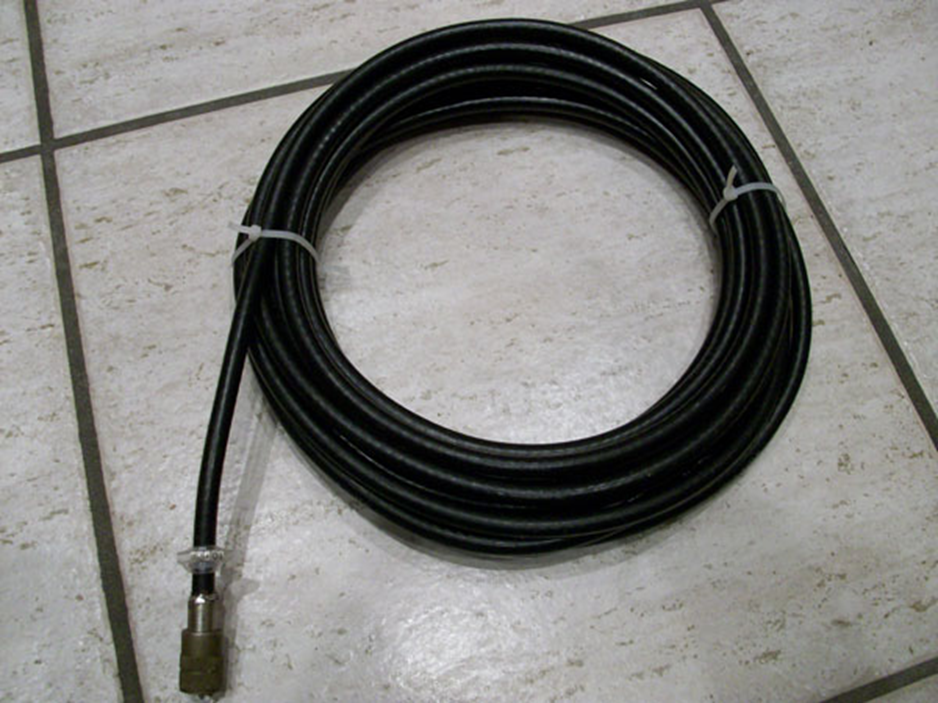
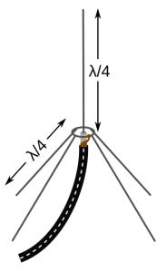
The stub consists of a piece of open or short coaxial cable transmission line on one side and connected, generally, to another transmission line on the other. The generally is not put at random, there are other types of more complex configurations. It is
usual to apply the stub
with a T at the point closest to the antenna terminal of the transceiver or amplifier. The stub length depending on use is usually ¼ or ½ electrical wave. As with PBs, stubs attenuate both receive and transmit.
The actual stub
length depends on the type of cable used and more specifically its speed factor. A high quality cable attenuates more than a low quality one, e.g. an RG213 has higher attenuations than an RG58. Depending on use, the end not connected to the circuit (or transmission line) can be short-circuited or left open.
Let’s take a practical example.
Suppose we cut a piece of RG213 at ¼ wave. Electrically, we have that the impedances at the two ends of the cable are opposite: if we leave the terminal side open, the input impedance will be very low, but if we short it at the input we will have a very high impedance.
If we cut the cable in ½ wave we will find that the impedance is the same on both ends, i.e. if we leave the terminal side open the impedance will be very high both at the input and at the end of the cable, on the contrary, if we short the terminal side, the impedance will be very low on both sides.
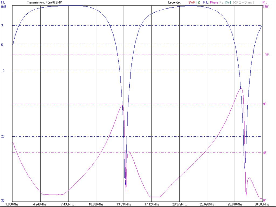
The image above shows the graph of a stub made with H200 ¼-wave cable shorted for 40 metres. The sky-blue curve shows two deep peaks on the 20- and 10-metre bands respectively, the former in the region of 28 dB, the latter slightly lower.
The other interesting thing to note concerns the 15-metre band: zero attenuation, in fact, falls right on the third harmonic of 7 MHz, making this filter available for both 40 and 15 metres by attenuating 14 and 28 MHz. As
you may have guessed, this stub is yes ¼ wave on 40, but of course it is also ½ wave on 20 metres. If you leave the stub’s end open, the work performed by the stub will be completely reversed, i.e. it will make 20 and 10 metres pass by attenuating 40 and 15 metres, at the expense of a slight shift in the working frequency.
The following diagram shows a stub for 160 metres built with RG58.
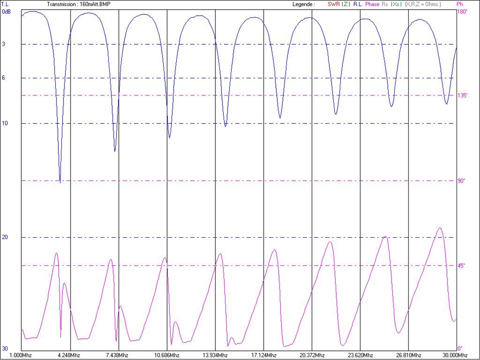
This stub is ¼ wave with short end side. We immediately observe that the quality of the cable “weighs” on the performance of a stub filter in coaxial cable, in fact, the attenuation of the second harmonic, at about 3,600 KHz, is just over 15 dB. This is gradually followed by the other attenuated harmonics from 40 to 10 metres with decreasing value.
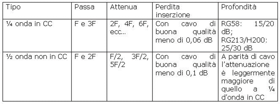
To end this first part, we will see summarised in a table how the two types of stub we have just seen
work, i.e. the ¼ wave short and the ½ wave open.
In the next “episode” we will see how to calibrate the stubs and how to couple them for greater attenuation.


1 thought on “Coaxial cable stubs (1st part)”
Comments are closed.